Danfoss VLT 5000 Instruction Manual
Browse online or download Instruction Manual for Noise Reduction Machine Danfoss VLT 5000. Danfoss VLT 5000 Instruction manual User Manual
- Page / 45
- Table of contents
- BOOKMARKS
- VLT 5000 Installation 1
- Startup Check List 1
- Reference Material 3
- Hp to kW Chart 4
- The Nameplates 5
- Pre-Installation Check 10
- Installation Checks 11
- Mounting the Drive 15
- Wiring the Drive 16
- • General Information 20
- • Motor Wiring 21
- – External 24Vdc 22
- – Load sharing for EB units 22
- • Control Wiring 23
- – Normally Open - Momentary 25
- 32 or 33 28
- • Digital Inputs – Continuous 30
- • Digital Inputs 31
- – SPDT Center OFF 32
- • Digital Inputs – Encoder 35
- • Analog Inputs – 0 to 10Vdc 36
- • Analog Inputs 37
- • Analog Outputs 41
- • Analog Output - Pulse 43
- • Digital/Relay Outputs 44
- • Serial Communications 45
Summary of Contents
1VLT 5000 InstallationStartup Check List• Reference material• Pre-Installation• Installation Checks•Wiring– Incoming Power– Motor–Brake– Control– Seri
10Pre-Installation Check• Check Motor Wiring– No power correction capacitors between drive and motor– 2-speed motors must be wired for full speed– Par
11Installation Checks• Fuses must be installed– Sized using Pages 34-35 in Instruction ManualTo comply with UL / cUL, fuses must be wired on the incom
12Installation Checks• Environmental Concerns– Clean and Dry– 24-Hour temperature limit – page 214– Altitude Limits – page 214The VLT 5000 can be supp
13Installation Checks• Mounting– Vertical– Flush Mounted OnlyIn order to provide proper cooling, the drive must always be mounted vertically.It is als
14Installation Checks• Mounting– Side by Side is acceptable– Needs space above and below driveThe VLT 5000 cools itself by drawing cooling air through
15Mounting the Drive• Keep the drive clean– Use dust covers to keep construction dust from getting into it– Remove the dust covers before applying pow
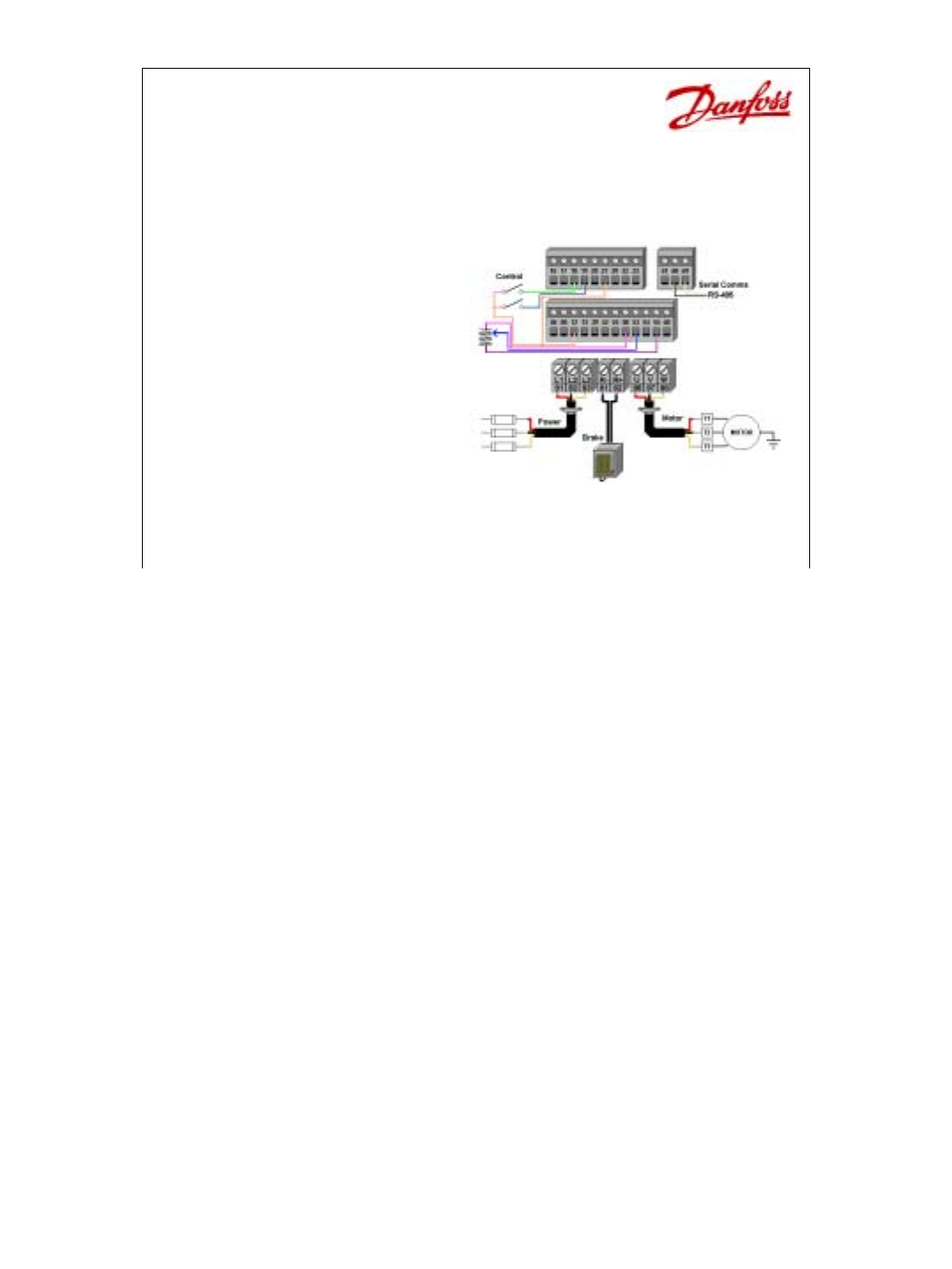
16Wiring the Drive• General Wiring• Power Input•Brake• Motor Output•Control• Serial CommsThis next section covers the wiring of the drive. The first
17Wiring the Drive• Conduit entry– All wiring enters the bottom of drive– Knock-outs are provided on many drives– Larger drives have a removable condu
18Wiring the Drive• At least three separate METALLIC conduits must be connected to the drive– Power into the drive [L1, L2, L3 and a ground back to th
19Wiring the Drive• Input fuses– All drives must have input fuses installed in the power supply to the drive– Refer to the Instruction Manual for fuse
2Touching the electrical parts may be fatal — even after the equipment has been disconnected from the AC line. To be sure that the capacitors have ful
20Wiring• General Information– Maximum voltage to control card is 24Vdc– Do NOT connect 120/240/460/575 to Control terminals– Use Relay 01, 02, 03 for
21Wiring• Motor Wiring– Use Terminals 96, 97, 98– Check torque – page 53– Distance limits – Disconnect OKA disconnect switch between the drive and mot
22Wiring• Brake Wiring on SB & EB units– Use Terminals 88 & 89 for resistor– Load sharing for EB units– External 24Vdc.On Standard with Brake
23Wiring• Control Wiring– Digital Inputs– Analog Inputs– Analog Output– Digital/Relay OutputsThis next section covers control wiring.It covers Digital
24Wiring• Digital Inputs – 12 to 27 Enable– Jumper terminal 12 (+24Vdc) to terminal 27 (enable command)– Without jumper, bottom line of the display r
25Wiring• Digital Inputs – Push button– Normally Open - Momentary– Functions: Latched Start (terminal 18 only)– Reset–JogPush-Button (PB) Switch – Nor
26Wiring• Digital Inputs – Push Button– Normally Closed - Momentary– Stop Inverse means loss of 24Vdc to that terminal, stops the motor.– If multiple
27Wiring• Digital Inputs – Push Button– Normally Closed (NC) - Momentary (Push Button)– Multiple stop commands can be wired in series to accommodate m
28Wiring• Digital Inputs – Pushbuttons - 3 Wire Start/Stop– Term. 18 (P 302) set to “Latched Start”– Term. 16 (P 300) set to “Stop Inverse” for termin
29Wiring• Digital Inputs – Pushbuttons - Changing the Reference– Pulsed Increase/Decrease Reference Speed– Term. 32 (P 306) set to “Speed UP”; Term. 3
3Reference Material• Instruction Manuals• Connection Diagram• Schematic DiagramThese three pieces of reference material might be available to you when
30Wiring• Digital Inputs – Continuous– Single-pole, double throw (SPDT)– 2-wire Start/Stop using term 18.– Reverse using term 19 (P 303) – P 200 set t
31Wiring• Digital Inputs– Multiple Starts from One command– Common connected, terminal 20, on each unit– Maximum of 200mVIn the example above, one swi
32Wiring• Digital Inputs – One switch ON/OFF and Direction– SPDT Center OFF– Terminal 18 (P 302) set for “Start”– Terminal 19 (P 303) set for “Start &
33Wiring• Digital Inputs – Preset Speeds– 4 Preset Speeds set in Parameters 215, 216, 217 and 218– 4-Position Switch using diodes for signal isolation
34Wiring• Digital Inputs– Changing Setups– 4-Position Switch and relay used for signal isolation– P 004 must be set to Multi Setup4-position with a re
35Wiring• Digital Inputs – Encoder – A Channel showing speed comes into term 33 (P 307)– B Channel showing direction comes into term 32 (P 306)– +24Vd
36Wiring• Analog Inputs – 0 to 10Vdc– Potentiometer– Term 53 (P 308) set to “Reference” by default– Term 54 (P 311) set to “No operation” by default–
37Wiring• Analog Inputs– Potentiometer– P 203 is Min – Max or –Max to +Max– P 215 sets offset, may be negativeIn the diagram to the left, parameters a
38Wiring• Analog Inputs– One Potentiometer feeds multiple drivesOne Pot controlling multiple drivesIn the example above, one potentiometer is used to
39Wiring• Analog Inputs– 2-wire Transmitter– Term 12 or 13 supplies power +24Vdc– Jumper 39 to 55 to connect commonsAnalog Input – 2-wire TransmitterT
4Hp to kW Chart• 1 Hp = 0.746kW• Each VLT 5000 can be under sized by 4 and over sized by 1 – but watch current limits.• This chart shows most of the P
40Wiring• Analog Inputs– 3-wire Transmitter– Term 12 or 13 supplies power +24Vdc– Transmitter’s Signal wired to terminal 60 (P 314 = Feedback).– Jumpe
41Wiring• Analog Outputs– Meter Indication– Terminal 42 and 45 set to AO or DO– If using 0-Fmax 0-20mA, meter trim is P 202.– New software – meter tri
42Wiring• Analog Outputs– Master/Slave (Leader/Follower)– AO of Master to AI of Slave– Use 0-Fmax 4-20mA, use P 202 on master to match slope.– Use P
43Wiring• Analog Output - Pulse– Master/Slave (Leader/Follower)– DO of Master to DI of Slave set for Pulsed Reference– Use 0-Fmax 0-32,000 pulses, set
44Wiring• Digital/Relay Outputs– Digital Output powered +24Vdc– Relay Outputs are dry (no power) contactsDigital OutputsTerminals 42 and 45 besides be
45Wiring• Serial Communications– Need repeater (amplifier) after 31 drives attached together– Dip switch settings 2 & 3 to OFF except for 2 bus en
5The NameplatesAll Drives – On the Top or Left Side of the DriveOutput Ratings of DriveCatalog NumberSales NumberSerial NumberThe drive has two identi
6Pre-Installation Check• Compare AFD model number with what was ordered.Catalog Order Number System (Found on page D 62 of the catalog)Example: VLT- 5
7Pre-Installation Check• Be sure the Line Power, AFD and Motor have the same voltage range• Insure that all hand tools and kits are available.Before i
8Pre-Installation Check• Record motor data information– Motor Power– Motor Voltage– Motor Frequency– Motor Current (FLA)– Motor Speed (RPM)Write down
9Pre-Installation Check• Always ensure that Drive can handle maximum current of the motor.• Example page 20 – VLT 5100 – CT, HOIt is always important
© 2020, manymanuals.com. All rights reserved. | 0.092 s |
 Manymanuals.com
 Manymanuals.de
 Manymanuals.fr
 Manymanuals.it
 Manymanuals.pl
 Manymanuals.cz
 Manymanuals.es
 Manymanuals-pt.com
Comments to this Manuals